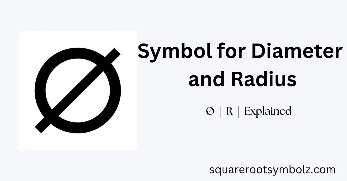
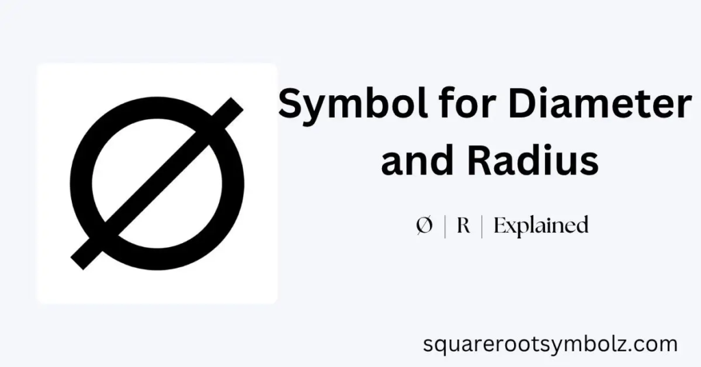
The symbol for diameter and radius is usually ⌀ or Ø for diameter and R for radius. These small marks tell you whether a dimension represents the full width across a circular feature or the distance from its center to its edge. In engineering drawings, that distinction matters because diameter, radius, tolerance, dimension lines, and circular features all communicate precise manufacturing information.
If you have ever looked at a drawing and wondered whether Ø25 and R25 mean the same thing, they absolutely do not. A 25-unit diameter has a 12.5-unit radius, while a 25-unit radius produces a 50-unit diameter. Understanding the notation makes technical drawings, CAD dimensions, hole callouts, and mechanical specifications much easier to read.
Dimension and tolerance symbols
The most common diameter notation is ⌀ or Ø, while the standard radius notation is R. A diameter callout such as ⌀20 identifies a circular feature with a nominal diameter of 20 units. A radius callout such as R20 identifies an arc or rounded feature with a radius of 20 units.
These symbols become even more important when tolerances are added. For example, ⌀20 ± 0.1 mm communicates a nominal diameter and its permitted variation. A radius may similarly appear as R10 ± 0.2 mm. The symbol tells the reader what type of measurement the numerical value represents before the tolerance is interpreted.
| Notation | Meaning | Example |
| ⌀20 | Diameter | 20-unit diameter |
| Ø20 | Common diameter representation | 20-unit diameter |
| R20 | Radius | 20-unit radius |
| SR20 | Spherical radius | 20-unit spherical radius |
| S⌀20 | Spherical diameter | 20-unit spherical diameter |
| ⌀20 ± 0.1 | Diameter with tolerance | Controlled circular size |
Components
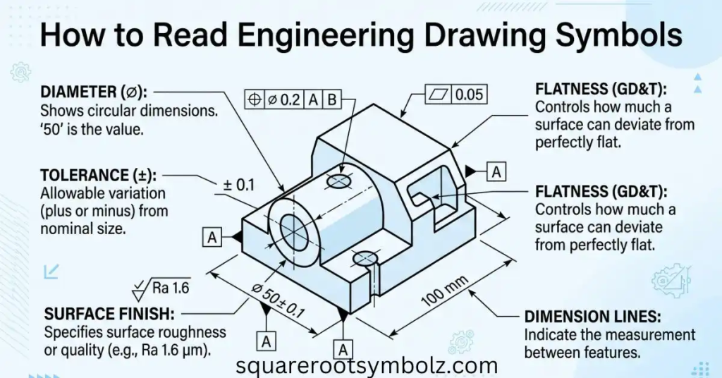
A technical drawing is not simply a picture with numbers scattered around it. Its dimension line, extension lines, arrows, symbols, and numerical values work together to communicate the intended size and location of a feature. Diameter and radius symbols are therefore part of a larger dimensioning language.
For a circular feature, the symbol provides an immediate semantic clue. ⌀20 means the measurement describes the diameter, whereas R20 means the measurement describes the radius. This is especially useful when a drawing contains several circles, arcs, holes, fillets, or rounded edges that might otherwise look similar.
Diameter dimension
A diameter measures the straight-line distance across a circle through its center. Mathematically:
d = 2r
So if a drawing specifies ⌀40 mm, the corresponding radius is 20 mm.
Radius dimension
A radius measures the distance from the center of a circle or arc to its curved boundary. The conventional notation is R, placed before the numerical value. ASME dimensioning guidance states that radius values are preceded by the appropriate radius symbol.
Dimensions and their types
Diameter and radius are both examples of dimensional information used to describe geometry. A drawing can contain linear dimensions, angular dimensions, diameters, radii, locations, tolerances, and other measurements. Each tells the manufacturer or inspector something different about the part.
The distinction becomes obvious with a simple part. Imagine a metal plate containing a circular hole and a rounded outside corner. The hole might be specified as ⌀10, while the corner could be specified as R5. One describes the complete width of the hole; the other describes the curvature of the corner.
Fundamental principles of dimensioned drawing
Good dimensioning is designed to make a drawing readable and manufacturable. Dimension lines should be organized, extension lines should communicate the measured feature clearly, and dimensions should be positioned so that the reader can understand them without guessing. Wikipedia’s technical-drawing reference lists principles covering line crossings, spacing, placement, and dimension readability.
For diameter and radius dimensions, clarity is especially important. A diameter symbol normally precedes its value, while R precedes a radius value. ASME guidance specifies that these symbols precede the dimension or tolerance value and are not separated from the value by a space.
Why the symbol comes first
Compare:
- ⌀25
- R25
The number is identical, but the geometry is completely different. The first describes a 25-unit diameter; the second describes a 25-unit radius. That small prefix therefore carries important engineering meaning.
Arrangement of dimensions
Dimensions should be placed where the relevant feature can be understood clearly. In technical drawings, the best view is normally the one that most directly describes the feature being dimensioned. Crowding too many dimensions into one area can make a drawing difficult to interpret.
For circular features, diameter and radius dimensions may use leaders or dimension lines directed toward the appropriate geometry. A radius dimension has a particularly recognizable convention: its dimension line points from the center toward the arc, with the arrowhead at the arc end. ASME describes this radius-dimension arrangement explicitly.
Technical drawing symbols: ISO vs ANSI standards
The exact conventions used in engineering documentation depend on the applicable drafting standard. In the United States, ASME Y14.5 is central to dimensioning and tolerancing practice, while ISO standards are widely used internationally. Buildref notes the broader distinction between US ANSI/ASME conventions and ISO-based practices.
The important point for a US-focused reader is not to assume that every drawing follows identical conventions. When working professionally, the governing drawing standard, company drafting practices, and project requirements take priority. The basic distinction between diameter and radius remains straightforward: diameter describes the full circular size; radius describes the distance from center to edge.
How to read engineering drawing symbols
Reading engineering symbols becomes much easier when you treat each symbol as a short instruction. ⌀ tells you to interpret the following value as a diameter; R tells you to interpret it as a radius. Buildref specifically explains that the diameter symbol precedes circular dimensions while R precedes arc-radius values.
Consider these examples:
⌀12 → 12-unit diameter
R12 → 12-unit radius
⌀25 ± 0.05 → controlled diameter
R8 ± 0.1 → controlled radius
4X ⌀6 → four circular features with 6-unit diameter
Once you recognize that relationship, many engineering drawings become much less intimidating.
⌀ vs Ø vs R
The characters can be confusing because technical software does not always display the same visual character. ⌀ is the dedicated Unicode Diameter Sign, while Ø is Latin capital O with stroke but is commonly used as a diameter representation in technical software. R is the conventional radius notation. Rhino, for example, provides separate diameter and radius annotation options.
Basic concepts and principles
The simplest way to remember the symbol for diameter and radius is this:
Diameter = ⌀ / Ø
Radius = R
Diameter is always twice the radius. If you know one, you can calculate the other using d = 2r. That relationship is fundamental in geometry and becomes practical when interpreting mechanical drawings, CAD models, pipe dimensions, holes, shafts, and rounded edges.
A useful mental picture is a wheel. If you measure straight across the center from one edge to the other, you are measuring the diameter. If you measure from the center to one edge, you are measuring the radius. The symbols simply tell the person reading the drawing which measurement they are looking at.
Quick Comparison
| Feature | Diameter | Radius |
| Symbol | ⌀ / Ø | R |
| Measures | Across the circle | Center to edge |
| Formula | d = 2r | r = d/2 |
| Example | ⌀30 | R15 |
| Common use | Holes, shafts, circles | Arcs, fillets, rounded corners |
| Symbol position | Before value | Before value |
Conclusion
The symbol for diameter and radius is simple once you know the rule: ⌀ or Ø indicates diameter, while R indicates radius. Diameter measures across a circle through its center, whereas radius measures from the center to the edge. Because diameter is twice the radius, ⌀40 and R40 describe very different sizes.
For engineering drawings, CAD models, manufacturing specifications, and technical documentation, these symbols are more than decorative marks. They remove ambiguity and tell the reader exactly how a numerical dimension should be interpreted. If you’re building a symbol-focused topical cluster, this page should naturally connect to your diameter symbol, radius symbol, dimension symbol, hole diameter symbol, diameter notation, and engineering drawing symbols pages.
FAQ Section
What is the symbol for diameter and radius?
The common symbol for diameter is ⌀ or Ø, while the radius symbol is R. Both normally appear before the numerical dimension.
What is the diameter symbol?
The dedicated diameter sign is ⌀. In many engineering drawings and CAD applications, Ø is also used to represent diameter.
What is the radius symbol?
The conventional radius symbol is R. For example, R10 means a radius of 10 units.
Is Ø the same as ⌀?
They are visually similar, but technically they are different Unicode characters. ⌀ is the dedicated Diameter Sign, while Ø is a Latin letter with a stroke. In technical practice, Ø is commonly used as a diameter representation.
Does the diameter symbol go before the number?
Yes. Engineering-dimensioning guidance places the diameter symbol before the numerical value, such as ⌀25.
Does the radius symbol go before or after the number?
The R goes before the radius value, such as R15. ASME guidance specifies that radius values are preceded by the appropriate radius symbol.
What is the difference between ⌀20 and R20?
⌀20 means a diameter of 20 units, while R20 means a radius of 20 units. Therefore, R20 corresponds to a 40-unit diameter.
What symbol is used for a hole diameter?
A hole’s size is commonly expressed with the diameter notation, such as ⌀10, meaning a nominal 10-unit diameter.
What does SR mean on an engineering drawing?
SR means spherical radius. It is used when the dimension refers specifically to the radius of a spherical feature.
What does S⌀ mean?
S⌀ indicates a spherical diameter. It distinguishes the diameter of a spherical feature from an ordinary cylindrical or circular diameter.

I’m the creator of SquareRootSymbolz.com, where I publish easy-to-understand guides on symbols, Unicode characters, Alt codes, keyboard shortcuts, and copy-and-paste text symbols. My goal is to provide accurate, well-researched, and user-friendly content that helps readers quickly find the information they need.