Diameter notation identifies a measurement as the full distance across a circular feature through its center, usually with the symbol ⌀ placed before the value. In engineering drawings, technical specifications, CAD annotations, and manufacturing documents, this small mark prevents a dimension from being mistaken for a radius or another measurement. ASME dimensioning guidance specifies that the diameter symbol precedes the diametral value.
If you’ve ever looked at a drawing such as ⌀25 and wondered whether the symbol meant a hole, radius, or something else, the answer is straightforward: it identifies 25 as a diameter. The challenge is that ⌀ is frequently confused with Ø, ∅, or φ, even though those characters have different identities and meanings.
Understanding the Diameter Symbol
The diameter symbol ⌀ is used before a numerical dimension to tell the reader that the stated value represents the diameter of a circular or cylindrical feature. For example, ⌀40 mm means the feature has a diameter of 40 millimeters. The notation is common in mechanical engineering, manufacturing, CAD, and technical drawings.
This distinction matters because diameter and radius describe different measurements. A circle with a ⌀40 mm diameter has a radius of 20 mm. If a drawing instead says R40, it specifies a radius of 40 mm and therefore a diameter of 80 mm. A tiny notation difference can completely change the required part size.
The Standard Diameter Symbol
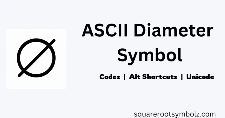
The dedicated Unicode character is ⌀, officially named DIAMETER SIGN, with code point U+2300 and decimal value 8960. It belongs to Unicode’s Miscellaneous Technical block. The character visually consists of a circle crossed by a diagonal stroke and is used for diameter indications in technical contexts.
In engineering notation, the symbol normally appears immediately before the dimension, such as ⌀12, ⌀25.4, or ⌀50 ± 0.1. ASME’s dimensioning guidance states that the diameter symbol precedes diameter values. This placement makes the meaning of the number immediately clear to designers, machinists, inspectors, and manufacturers.
Diameter notation in a simple example
Consider a drawing containing the callout ⌀20 mm. The number 20 describes the straight-line distance across the circular feature through its center, not the distance from the center to its edge. Therefore, the corresponding radius is 10 mm.
Similar Symbols and Differences
One of the most important details in diameter notation is understanding that similar-looking characters are not necessarily interchangeable. ⌀ is the dedicated Diameter Sign, Ø is Latin Capital Letter O With Stroke, ∅ represents the empty set in mathematics, and φ/Φ are Greek phi characters. Their appearance can be confusing, but their Unicode identities and meanings differ.
In everyday technical work, Ø is frequently used as a diameter substitute, particularly in software, text, and older documentation. However, when precision matters, the actual ⌀ U+2300 character is the dedicated diameter sign. The correct choice can depend on the applicable drafting standard, software, and established documentation practices.
| Character | Unicode | Primary meaning |
| ⌀ | U+2300 | Diameter Sign |
| Ø | U+00D8 | Latin capital O with stroke |
| ø | U+00F8 | Latin small o with stroke |
| ∅ | U+2205 | Empty set |
| φ | U+03C6 | Greek small phi |
| Φ | U+03A6 | Greek capital phi |
The distinction is more than cosmetic. Using the wrong character can create ambiguity in searchable digital documents, engineering databases, or standards-controlled technical documentation.
How to Type the Diameter Symbol
The easiest way to insert diameter notation depends on your operating system and application. On Windows, Unicode input, Character Map, and application-specific symbol dialogs are common choices. On Mac, Character Viewer is practical. Word supports Unicode conversion, while CAD programs may provide their own diameter commands.
For Windows, one commonly documented method is Alt + 8960 using the numeric keypad. However, Alt-code behavior can vary by application and character encoding, so it should not be treated as universally reliable for every program. If it fails, copy-paste, Character Map, or a Unicode-aware insertion method is safer.
Unicode method
The hexadecimal Unicode value for ⌀ is 2300. In applications supporting Microsoft’s Alt+X conversion, typing 2300 followed by Alt + X can convert the code into ⌀. This is especially useful in Microsoft Office applications and avoids depending on a dedicated numeric keypad.
Character Map
Windows Character Map is another reliable visual method. Open Character Map, search for the diameter character or navigate through available Unicode characters, select ⌀, copy it, and paste it into the required application. This is particularly useful when keyboard shortcuts behave differently.
Mac Character Viewer
On macOS, open the Character Viewer with Control + Command + Space, search for “diameter,” and select the required character. This approach is useful because the dedicated diameter sign is not normally printed on a standard Mac keyboard.
Technical Usage
Diameter notation appears wherever the exact size of a circular or cylindrical feature needs to be communicated. Common examples include holes, shafts, pipes, bores, pins, cylinders, circular bosses, and machined features. MIT’s engineering drawing material, for example, uses the diameter indication when dimensioning a hole.
In GD&T, the diameter symbol has an additional role. When it appears in a feature control frame, it indicates that the associated tolerance zone is cylindrical. That means the symbol is not merely decorative shorthand; its presence can change how the geometric tolerance is interpreted.
Diameter notation in engineering drawings
A callout such as ⌀10 tells a manufacturer that the circular feature has a nominal diameter of 10 units, with the drawing’s units and tolerance requirements determining the acceptable size. A hole specified as 5X ⌀1.2 means five holes, each having a nominal diameter of 1.2 units; this interpretation is also reflected in practical engineering discussions of drawing notation.
Should I put the diameter symbol before or after the measurement?
The standard convention is to place the diameter symbol before the numerical value, such as ⌀25 mm, rather than after it. This immediately tells the reader that 25 is a diametral dimension. ASME guidance likewise specifies that the diameter symbol precedes diameter values.
For example:
- Correct: ⌀25 mm
- Not standard: 25 mm ⌀
The same principle applies when tolerances are included. The symbol establishes the type of dimension first, followed by the nominal value and its tolerance information.
How do I write diameter with tolerances?
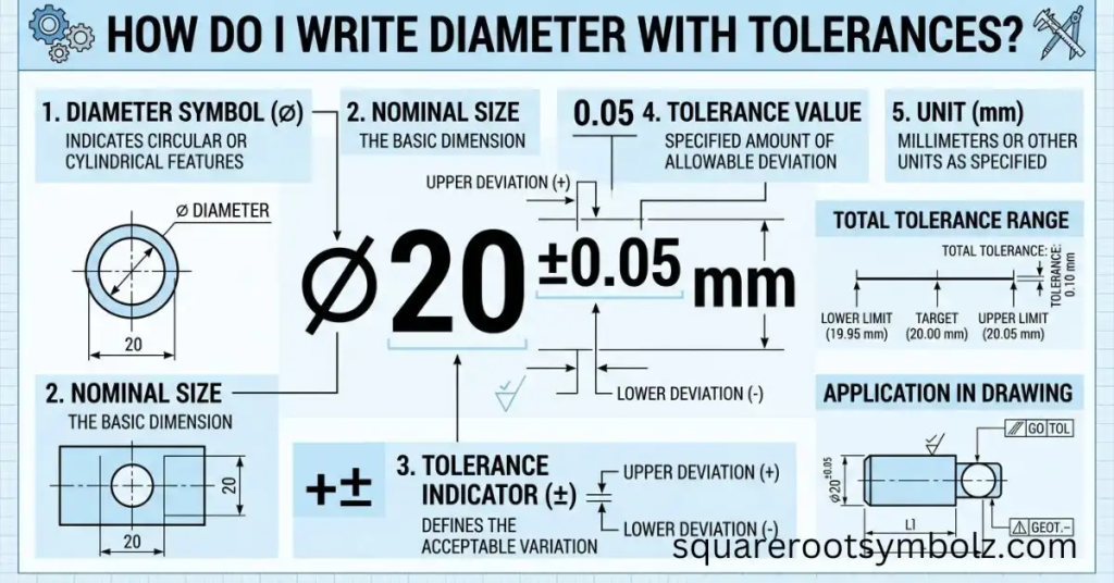
A diameter may be written with a tolerance to define the acceptable manufacturing range. For example, ⌀50 ± 0.1 mm indicates a nominal diameter of 50 mm with a plus-or-minus tolerance of 0.1 mm. A bilateral tolerance can also be expressed as ⌀50 +0.1/−0.05 mm.
The tolerance is important because a nominal dimension alone does not always tell a manufacturer exactly what range is acceptable. Engineering drawings may use bilateral tolerances, limit dimensions, or general tolerances specified elsewhere in the drawing. The applicable engineering standard and drawing notes determine how the value should be interpreted.
Diameter and radius are not interchangeable
A diameter is twice the radius:
d = 2r
So if a drawing specifies ⌀30 mm, its radius is 15 mm. Conversely, R30 describes a 30 mm radius and therefore corresponds to a 60 mm diameter for a complete circle.
Can I use the diameter symbol in CAD software?
Yes. Modern CAD applications generally provide ways to insert diameter notation directly into dimension annotations. Some software has a dedicated diameter symbol option, while others support keyboard codes or internal text commands. AutoCAD, for example, uses %%C as a legacy diameter-symbol control code in text and dimension contexts.
CAD notation is particularly important because the symbol can be part of an intelligent dimension rather than ordinary text. When the drawing is updated, the dimensioning system can maintain the relationship between the geometry and its annotation. That is one reason CAD workflows are preferable to manually typing measurements beside geometry.
AutoCAD and Technical Drawing Software
AutoCAD provides a dedicated diameter notation workflow through its dimensioning and text systems. The commonly documented %%C code can be used in appropriate text contexts to generate the diameter symbol. Other CAD programs use their own symbol palettes, dimension settings, or annotation controls.
For professional drawings, the safest approach is to use the CAD application’s native dimensioning functionality whenever possible. This keeps the diameter information associated with the geometry and reduces errors caused by manually typed annotations.
Technical Documentation and Markup
Diameter notation also appears in digital technical documentation. The Unicode character can be represented directly as ⌀, or encoded using its decimal HTML reference ⌀ or hexadecimal reference ⌀. The Unicode code point is U+2300.
This matters for websites, databases, engineering software, and documentation systems because character encoding determines whether the symbol displays correctly. If a font does not support U+2300, the character may appear as a square, replacement character, or another fallback glyph. Using Unicode-capable fonts and proper encoding helps preserve the intended notation.
Diameter notation in HTML
For web content, you can write the actual character:
⌀25
or use:
⌀25
The hexadecimal form is:
⌀25
All three approaches represent the Diameter Sign when correctly interpreted as Unicode.
Using the Empty Set as a Diameter Symbol Substitute
The empty set symbol ∅ is sometimes confused with or substituted for the diameter sign because the two characters look similar. However, they are not the same character. ∅ U+2205 represents the empty set in mathematics, whereas ⌀ U+2300 is the Diameter Sign.
Likewise, Ø is technically a letter rather than the Unicode Diameter Sign. Despite this, Ø appears frequently in practical engineering communication as a diameter substitute. If you’re preparing a standards-controlled drawing, always follow the relevant drafting standard and your organization’s conventions rather than relying solely on visual similarity.
Quick Reference Table
| Diameter notation | Meaning | Example |
| ⌀25 | 25-unit diameter | Circular feature |
| R25 | 25-unit radius | Arc or radius |
| ⌀50 ± 0.1 | Diameter with tolerance | Manufacturing dimension |
| 5X ⌀10 | Five features, each 10 diameter | Hole pattern |
| ⌀20 THRU | 20-unit through feature | Through-hole callout |
For a quick rule, remember this:
⌀ tells you “diameter,” while R tells you “radius.”
That simple distinction prevents one of the most expensive interpretation mistakes in technical drawings: manufacturing a feature at twice or half the intended size.
Conclusion
Diameter notation is a compact but essential part of engineering communication. The symbol ⌀ tells the reader that the following value represents a diameter, while R identifies a radius. In professional drawings, placing the diameter symbol before the numerical value removes ambiguity and helps designers, machinists, inspectors, and manufacturers interpret the same dimensional requirement correctly.
The most important distinction to remember is ⌀ vs Ø vs ∅. They may look similar, but they are different Unicode characters with different meanings. For standards-driven technical work, use the notation required by the applicable standard; for everyday communication, recognize that Ø is often used as a practical substitute. Understanding that small difference makes your drawings, specifications, CAD annotations, and technical documents much more precise.
FAQ Section
What does diameter notation mean?
Diameter notation identifies a dimension as the full distance across a circular feature through its center. The dedicated Diameter Sign is ⌀, normally placed before the numerical value.
What is the correct diameter symbol?
The dedicated Unicode Diameter Sign is ⌀ U+2300. However, Ø is frequently used as a practical substitute in engineering and technical documents.
Does ⌀ mean diameter?
Yes. ⌀ is the Unicode Diameter Sign and is used to indicate the diameter of circular or cylindrical features in technical notation.
Does Ø mean diameter?
Ø technically represents Latin Capital Letter O With Stroke, not the Unicode Diameter Sign. Nevertheless, it is commonly used as a diameter notation substitute in engineering and technical contexts.
Is ∅ a diameter symbol?
No. ∅ is the empty set symbol, used in mathematics and set theory. It is visually similar to the diameter sign but has a different Unicode code point and meaning.
Does the diameter symbol go before the number?
Yes. Standard technical notation places the diameter symbol before the dimension, such as ⌀25. ASME guidance specifically states that the diameter symbol precedes diameter values.
What is the difference between diameter and radius notation?
Diameter measures across a circle through its center, while radius measures from the center to the edge. The diameter is twice the radius, so ⌀40 corresponds to R20.
Where is diameter notation used?
It is widely used in engineering drawings, mechanical design, manufacturing, machining, CAD, technical specifications, inspection documents, and GD&T.
What does ⌀50 mean?
⌀50 means the circular or cylindrical feature has a nominal diameter of 50 units. The actual unit such as millimeters or inches is determined by the drawing or specification.
What does 5X ⌀10 mean?
It means there are five features, each having a nominal diameter of 10 units. In a hole pattern, for example, it commonly indicates five holes of the specified diameter.

I’m the creator of SquareRootSymbolz.com, where I publish easy-to-understand guides on symbols, Unicode characters, Alt codes, keyboard shortcuts, and copy-and-paste text symbols. My goal is to provide accurate, well-researched, and user-friendly content that helps readers quickly find the information they need.