The hole diameter symbol is ⌀, commonly represented as Ø in engineering drawings and CAD software, and it tells you that the following dimension describes a hole’s diameter. For example, ⌀10 means a circular hole with a 10-unit diameter. Engineering drawings use this notation to communicate hole size clearly for manufacturing, inspection, and assembly.
If you’ve ever looked at a mechanical drawing and wondered whether Ø10 meant a hole, shaft, radius, or something else, the surrounding callout provides the answer. In this guide, we’ll connect diameter notation, simple holes, hole depth, through holes, blind holes, threaded holes, counterbores, countersinks, tolerances, and CAD callouts so the symbol makes sense instead of looking like another mysterious engineering mark.
Simple Hole
A simple hole is a basic cylindrical opening without special features such as threads, counterbores, or countersinks. In engineering, its size is normally communicated through a diameter dimension. The hole may be drilled, bored, molded, or otherwise manufactured depending on the material and production process.
The key idea is simple: when the feature is circular, the diameter describes its width across the opening through its center. A drawing might show Ø10, meaning the hole is 10 units in diameter. The unit itself comes from the drawing’s stated measurement system, such as inches or millimeters.
What Is a Simple Hole?
A simple hole is a circular opening cut into a component. It can function as a clearance passage for a bolt, a locating feature for a pin, an opening for a shaft, or a pathway for a fluid or cable. Unlike specialized holes, it has no additional recess or internal thread.
Imagine a flat steel plate with one clean circular opening. If a drawing labels that opening Ø12 THRU, you know two important things immediately: its diameter is 12 units and it passes completely through the plate. That is far more precise than simply writing “make a hole.”
What Is the Symbol for a Simple Hole?
The diameter symbol used for a simple hole is commonly written as Ø or ⌀, placed immediately before the numerical diameter. Thus, Ø8 or ⌀8 tells the manufacturer that the dimension represents an 8-unit diameter rather than a linear width.
Strictly speaking, ⌀ is the Unicode Diameter Sign, while Ø is the Latin capital letter O with stroke. They look extremely similar and are commonly used interchangeably in technical contexts, but they are different characters. When standards or software matter, use the symbol supported by the relevant system.
How Are Simple Holes Shown on Engineering Drawings?
Simple holes are normally shown with their diameter and, where necessary, their depth. A through hole can be identified with THRU, while a blind hole requires a depth indication. The drawing may use a leader line pointing directly to the circular feature.
For example, Ø10 THRU means a 10-unit hole passing completely through the material. A blind-hole callout may instead specify a diameter followed by a depth. This distinction matters because the same diameter can describe two very different manufacturing operations.
How Are Hole Sizes Specified in Engineering Drawings?
Hole sizes are specified primarily through diameter and depth, with tolerances and feature information added when manufacturing requires greater control. Xometry notes that proper hole specifications are important for functionality, fit, assembly, and manufacturing accuracy.
A drawing may therefore communicate considerably more than just Ø10. Depending on the feature, the callout can identify whether the hole is through or blind, its depth, thread specification, counterbore, countersink, quantity, and allowable dimensional variation.
A useful way to read a hole specification is:
| Drawing information | What it tells you |
| Ø10 | Hole diameter is 10 |
| THRU | Hole passes through the material |
| Depth value | How deep a blind hole extends |
| M10 × 1.5 | Metric thread designation |
| 6X | Six repeated features |
| ⌴ | Counterbore feature |
| ⌵ | Countersink feature |
| Tolerance | Allowed dimensional variation |
This is why the hole diameter symbol should not be interpreted in isolation. The surrounding callout provides the manufacturing story.
What Do Hole Diameter Symbols Indicate?
The hole diameter symbol indicates that the number following it represents a diameter, not a radius or ordinary linear distance. On an engineering drawing, ⌀10 tells the reader that the circular feature has a 10-unit diameter. Xometry specifically describes the diameter symbol as identifying the size of circular holes.
The symbol is especially useful because a circular feature can appear visually smaller or larger depending on the drawing view. Rather than relying on appearance, the dimension gives an exact manufacturing requirement. This helps designers, machinists, inspectors, and engineers work from the same information.
The diameter symbol also appears in more complicated callouts. A counterbored or countersunk feature may contain multiple diameter values because different portions of the hole have different sizes. Biology Insights gives examples where the primary hole diameter is followed by counterbore or countersink information.
C=2πr
C=2πr=2π(3.00)=18.85C=2\pi r=2\pi(\text{3.00})=\text{18.85}C=2πr=2π(3.00)=18.85
rrr
rrr
circumferencer = 3.00
Give feedback
For a simple circular hole, remember the geometry: diameter = 2 × radius. If the hole diameter is 20 mm, its radius is 10 mm. That relationship becomes useful when converting drawing dimensions into calculations for area, clearance, or other circular geometry.
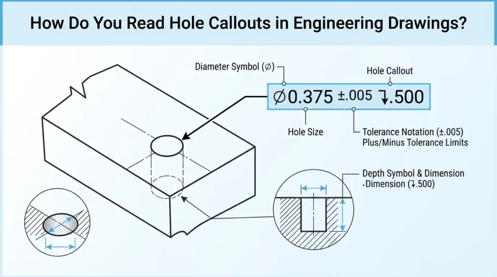
How Do You Read Hole Callouts in Engineering Drawings?
Start with the hole symbol, then identify the diameter, followed by any depth, thread, feature, quantity, or tolerance information. Xometry recommends examining these elements together because a complete hole callout communicates more than just the opening size.
Consider a simplified callout such as 6X Ø0.375 THRU. The 6X means six instances, Ø0.375 gives the diameter, and THRU tells the manufacturer that each hole passes completely through the material. Biology Insights uses this same type of multi-hole notation when discussing hole patterns.
Reading a Blind Hole
A blind hole stops inside the material rather than exiting the opposite surface. Its callout therefore needs both the hole diameter and an indication of depth. This is different from a through hole, where the word THRU can communicate that the hole continues through the component.
For example, a drawing might communicate a Ø8 blind hole with a specified depth. The diameter tells the machinist the size of the opening; the depth controls how far the tool must penetrate. Confusing these two values can produce a part that looks correct from above but fails during assembly.
Reading a Threaded Hole
Threaded holes require more information than simple drilled holes because the internal thread must match a mating fastener. Metric callouts commonly begin with M, followed by nominal diameter and pitch, such as M10 × 1.5. Inch thread callouts use different conventions, including thread count and series.
This creates an important distinction: the diameter symbol used for a plain hole does not automatically tell you the final thread specification. A threaded-hole callout communicates the thread standard and pitch so the correct tap, drill process, and fastener relationship can be established.
What Information Is Included in Hole Callout Symbols?
A complete hole callout can communicate type, diameter, depth, quantity, threading, special geometry, and tolerance. The exact combination depends on what the part needs. Xometry specifically identifies type, size, depth, and tolerance as important components of hole-callout information.
For example, a basic through hole might need only diameter and THRU, while a counterbored hole requires additional information describing the larger recess. A threaded blind hole can require still more details because the drawing must distinguish drill diameter, thread size, pitch, and respective depths.
| Hole feature | Typical information |
| Simple hole | Diameter |
| Through hole | Diameter + THRU |
| Blind hole | Diameter + depth |
| Threaded hole | Thread size + pitch + depth where required |
| Counterbore | Hole diameter + counterbore diameter + depth |
| Countersink | Hole diameter + countersink diameter + angle |
| Hole pattern | Quantity + diameter + location |
| Precision hole | Size + tolerance + location requirements |
The practical lesson is worth remembering: Ø tells you diameter, but the complete callout tells you what the manufacturer must actually make.
Dimensioning Hole Patterns
When several holes repeat across a component, engineering drawings usually avoid writing the same dimension over and over. Instead, the drawing can identify the quantity and define the pattern. A notation such as 6X Ø0.375 THRU communicates six identical through holes of the specified diameter.
Circular patterns are often arranged around a bolt circle, where the centers of the holes lie on an imaginary circle. The drawing can specify the bolt-circle diameter, number of holes, angular spacing, and individual hole size. This keeps complicated patterns readable without sacrificing manufacturing information.
For rectangular patterns, X and Y coordinates can locate holes from a datum or reference edge. When positional accuracy matters, the drawing may also use geometric tolerancing to control how far the actual hole centers can deviate from their theoretically exact locations.
Hole Diameter Symbol Quick Reference
| Symbol / notation | Meaning | Example |
| ⌀ | Diameter Sign | ⌀10 |
| Ø | Common diameter notation | Ø10 |
| R | Radius | R5 |
| THRU | Hole passes through | Ø10 THRU |
| M | Metric thread designation | M10 × 1.5 |
| 6X | Six repeated features | 6X Ø5 |
| ⌴ | Counterbore | Ø6 ⌴ Ø12 |
| ⌵ | Countersink | Ø6 ⌵ Ø12 |
| ↧ | Depth-related notation in some systems | Ø8 ↧15 |
Ø vs ⌀
Although Ø and ⌀ look almost identical, they are not the same Unicode character. ⌀ is the Diameter Sign, while Ø is the Latin capital letter O with stroke. Engineering software and technical documentation frequently display Ø as the diameter notation, while standards or digital text systems may distinguish the characters.
If your goal is simply to copy a diameter symbol for a drawing or document, ⌀ is the safest character to identify explicitly as the Unicode Diameter Sign. If you’re working inside CAD software, however, the application’s drafting standard and font may control how the diameter character is rendered.
FAQ Section
What is the hole diameter symbol?
The common hole diameter symbol is ⌀, frequently displayed as Ø in engineering drawings and CAD applications. It is placed before a number to show that the dimension represents diameter.
What does Ø mean on a drawing?
Ø means diameter. For example, Ø10 indicates a circular feature with a 10-unit diameter.
Is ⌀ the same as Ø?
They look nearly identical but are technically different characters. ⌀ is the Unicode Diameter Sign, while Ø is Latin capital O with stroke. Both are commonly seen as diameter notation.
How do you dimension a hole on an engineering drawing?
A basic circular hole is normally dimensioned by its diameter, often preceded by Ø or ⌀. Additional notation can specify depth, threading, counterbores, countersinks, quantity, and tolerances.
What does Ø10 THRU mean?
Ø10 THRU means a circular hole with a 10-unit diameter that passes completely through the material.
What is the symbol for a blind hole?
A blind hole does not have one universal standalone diameter symbol. Its callout normally uses the diameter symbol plus a depth specification to show both opening size and penetration depth.
What is the difference between Ø and R?
Ø indicates diameter, while R indicates radius. A diameter measures across the full circle; a radius measures from the center to the edge.
What does 6X Ø0.375 THRU mean?
It means there are six holes, each having a 0.375-unit diameter, and all six holes pass completely through the material.
What symbol is used for a counterbore?
The commonly used counterbore symbol is ⌴. A counterbore callout can combine the hole diameter with the counterbore diameter and depth.
What symbol is used for a countersink?
The commonly used countersink symbol is ⌵. A countersink callout can include the through-hole diameter, countersink diameter, and included angle.
Do all holes use diameter?
No. Circular holes are normally defined by diameter, but slots and irregular openings require other dimensions such as width and length.
How are threaded holes dimensioned?
Threaded holes use thread-specific notation. Metric examples commonly use M + diameter + pitch, such as M10 × 1.5, while inch threads use conventions involving nominal size, threads per inch, series, and fit.

I’m the creator of SquareRootSymbolz.com, where I publish easy-to-understand guides on symbols, Unicode characters, Alt codes, keyboard shortcuts, and copy-and-paste text symbols. My goal is to provide accurate, well-researched, and user-friendly content that helps readers quickly find the information they need.