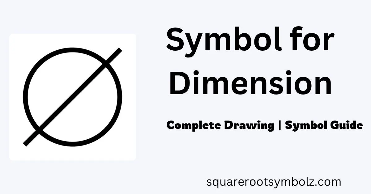
The symbol for dimension depends on what you are measuring: Ø identifies diameter, R identifies radius, and other drafting symbols specify depth, taper, chamfer, or related features. If you are reading a blueprint and a small mark beside a number leaves you guessing, you are not alone. Engineers and machinists rely on these dimensioning symbols, technical drawing notation, and engineering drawing conventions to communicate exact feature sizes. This guide explains the most useful diameter symbol, radius symbol, hole callout, and dimension line conventions in plain English, with examples grounded in established drafting practice.
There is another meaning worth knowing: in physics and dimensional analysis, a dimension is represented by symbols such as L for length, M for mass, and T for time. That is different from a drafting symbol placed before a numerical measurement. Understanding the distinction between quantity dimensions, engineering dimensions, dimension values, and measurement units prevents one of the easiest mistakes to make when researching this topic. NIST lists the seven SI base-dimension symbols as L, M, T, I, Θ, N, and J.
The quick chart
If you need an answer quickly, this table gives the most useful dimension symbols, their names, and what they communicate. In an engineering drawing, the symbol works together with a numerical value; for example, Ø20 communicates a 20-unit diameter, while R10 communicates a 10-unit radius. The surrounding dimension line, feature, and applicable tolerance complete the meaning.
| Symbol | Meaning | Example | What it tells you |
| Ø | Diameter | Ø20 | Circular feature is 20 units across |
| R | Radius | R10 | Arc or rounded feature has 10-unit radius |
| SØ | Spherical diameter | SØ30 | Spherical feature is 30 units in diameter |
| SR | Spherical radius | SR15 | Spherical radius is 15 units |
| □ | Square | □12 | Square cross-section is 12 units |
| ↧ | Depth | ↧20 | Feature depth is 20 units |
| ⌴ | Counterbore/spotface | ⌴ Ø12 | Specifies a counterbore or spotface |
| ⌵ | Countersink | ⌵ Ø12 | Specifies a countersunk feature |
| ° | Angle | 45° | Angular measurement |
| ± | Plus/minus tolerance | 50 ±0.1 | Permitted variation |
| (50) | Reference dimension | (50) | Informational/reference value |
| 4× | Repetition | 4× Ø10 | Four identical features |
The important point is that no single mark means “dimension” in every situation. The symbol identifies what kind of dimension the number represents. That distinction is why a reader should never interpret a number alone without looking at its symbol, feature, leader, tolerance, and drawing convention.
Ø, R and their spherical cousins
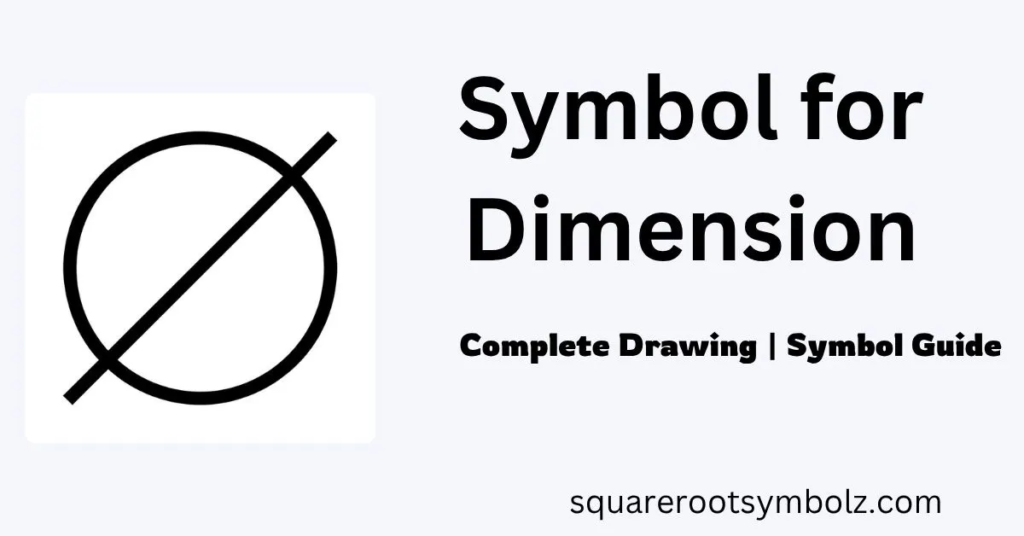
The Ø diameter symbol precedes a diametral value. A callout such as Ø12 means the circular feature measures 12 units across its diameter. The R radius symbol works differently: R6 means the referenced arc or rounded feature has a six-unit radius. These are among the most frequently encountered dimension symbols on engineering drawings.
Spherical features use additional notation. SØ identifies spherical diameter, while SR identifies spherical radius. This matters because a spherical surface is three-dimensional, whereas an ordinary R callout normally describes an arc or rounded feature. A simple prefix therefore changes the geometric interpretation of the dimension value, which is why these symbols should be read carefully rather than treated as decorative marks.
Hole callouts: ⌴, ⌵ and depth
Hole callouts combine several dimension symbols into a compact manufacturing instruction. A diameter symbol may identify the drilled size, while the counterbore, countersink, and depth symbols describe modifications to the hole. For example, a callout such as Ø6.6 THRU, ⌴ Ø11 ↧6 can communicate the through-hole diameter, counterbore diameter, and counterbore depth in one sequence.
The practical lesson is to read the callout in order rather than trying to decode each character independently. A counterbore creates a flat-bottomed enlargement, while a countersink creates a conical enlargement. Depth tells the reader how far a feature extends from the surface. These hole symbols, diameter dimensions, depth callouts, and feature descriptions work together to give a machinist enough information to manufacture the feature correctly.
Chamfer callouts
A chamfer is a beveled edge rather than a rounded edge. Common chamfer dimensions describe the size of the bevel and, when necessary, its angle. A notation such as 2 × 45° communicates a 2-unit leg with a 45-degree angle; some drawing conventions also use a compact C2 representation for a 45-degree chamfer.
This distinction is especially useful when reading a hole or edge callout. A countersink can look similar to a chamfer because both involve an angled surface, but their purposes differ. The countersink is associated with a hole and is commonly intended to accommodate a fastener head; a chamfer generally removes a sharp edge or prepares a feature for assembly.
Taper and slope
Taper and slope describe controlled changes in geometry rather than simple linear size. A conical taper relates diameter change to length, while slope describes a change in height along a flat inclined surface. These dimensioning symbols, inclined features, ratios, and technical callouts help manufacturing personnel understand geometry without requiring the drawing to show every detail pictorially.
The difference becomes easier to remember when you connect each symbol to the feature it describes. A tapered shaft, socket, or cone involves a round geometry; an inclined wedge or flat surface involves slope. The drawing therefore communicates not merely “this surface is angled,” but the intended geometric relationship and its measurable value.
Thread callouts
Thread callouts use compact notation to communicate thread size, diameter, pitch, tolerance class, and sometimes length or thread series. Examples include metric forms such as M10 × 1.5 and Unified thread designations such as 3/8-16 UNC. The surrounding notation determines whether the drawing is describing a metric, inch, internal, external, coarse, or fine thread.
A common mistake is trying to infer thread details from the apparent size of the drawing. Engineering drawings are not necessarily drawn at a scale that permits reliable measurement from the image. The thread callout, not a ruler placed against the screen, carries the manufacturing information. This is one reason dimension symbols and numerical callouts are central to technical documentation.
The small print: 4x, (), NTS and friends
Small modifiers can dramatically change how a dimension value should be interpreted. 4× or 6× indicates repetition, parentheses commonly identify a reference dimension, and NTS means the drawing should not be measured to scale. A value in parentheses is generally informational rather than the controlling dimension.
These details matter because a technically correct drawing can still be misunderstood if its modifiers are ignored. A note such as 4× Ø10 means four identical 10-unit circular features, while (50) is a reference value. When reading a blueprint, look beyond the primary dimension symbol and inspect counts, tolerances, notes, units, and the title block.
Reading a callout end to end
Consider the practical example 4× Ø6.6 THRU ⌴ Ø11 ↧6.5. The first part says there are four identical features; Ø6.6 gives the drilled diameter; THRU indicates the hole passes through; the counterbore symbol identifies the enlarged upper feature; Ø11 gives its diameter; and ↧6.5 gives its depth.
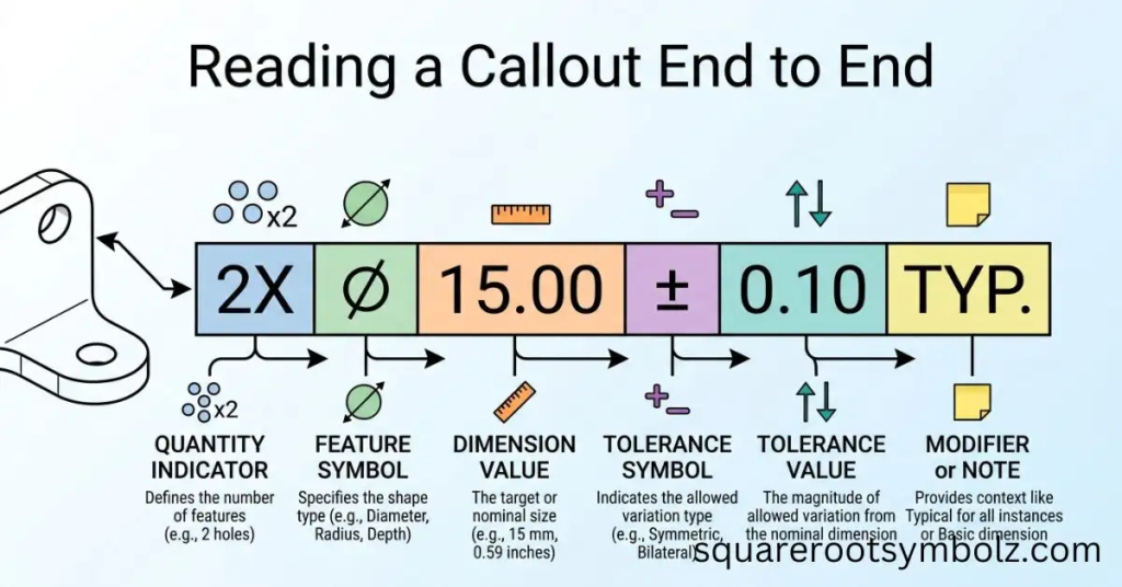
This is the real power of engineering notation. Instead of writing a paragraph describing a hole, the designer compresses the manufacturing requirements into a standardized dimension callout. When you read the symbols from left to right and connect each one to the feature it modifies, a drawing becomes far less intimidating. The numbers stop looking like isolated measurements and start forming a precise manufacturing instruction.
Where GD&T takes over
Dimension symbols primarily communicate size and dimensional information; GD&T adds controls for geometric characteristics such as form, orientation, location, and runout. This distinction is important because a basic size such as 50 mm does not, by itself, describe every way a manufactured feature may deviate from ideal geometry.
For example, a drawing may specify a size and separately control position, flatness, parallelism, or another geometric characteristic. Those controls belong to the GD&T system rather than ordinary size dimensioning. In US manufacturing, ASME Y14.5 is a major reference for dimensioning and tolerancing practice; ISO standards provide corresponding international frameworks.
Dimensioning conventions
Dimensioning conventions determine how dimension lines, extension lines, leaders, numerical values, symbols, and tolerances work together. On an engineering drawing, a dimension is not merely a number placed near a feature. Its location and accompanying notation tell the reader what geometry the value applies to and how that value should be interpreted.
The distinction between the dimension symbol and the unit is especially important. Ø20 might describe a diameter of 20 millimeters, inches, or another drawing unit depending on the document. The symbol tells you the geometric property; the drawing’s unit convention tells you the measurement system. Always check the title block, notes, or stated units before manufacturing or inspection.
Dimensioning and tolerancing symbols
A complete drawing can contain many categories of symbols: diameter, radius, depth, counterbore, countersink, arc length, slope, conical taper, and GD&T characteristics such as flatness, straightness, position, and perpendicularity. ConceptDraw’s reference library demonstrates how extensive this symbolic vocabulary becomes in mechanical design.
For readers searching for the symbol for dimension, the key is therefore to identify the feature first. Ask: Is it a diameter, radius, depth, angle, square, hole feature, or geometric tolerance? Once the feature is identified, the appropriate symbol becomes much easier to select. That approach is safer than memorizing isolated characters without understanding their engineering relationships.
The Other Meaning Symbols for Dimensions in Physics
There is an important second interpretation of this keyword that should not be ignored.
In dimensional analysis, the word “dimension” has a different technical meaning from a drawing dimension. The International System of Quantities uses conventional symbols for the dimensions of seven base quantities. NIST lists them as follows: L for length, M for mass, T for time, I for electric current, Θ for thermodynamic temperature, N for amount of substance, and J for luminous intensity.
| Base quantity | Symbol for dimension |
| Length | L |
| Mass | M |
| Time | T |
| Electric current | I |
| Thermodynamic temperature | Θ |
| Amount of substance | N |
| Luminous intensity | J |
These symbols are not engineering-drawing callouts such as Ø or R. They describe the dimension of a physical quantity. For example, area has dimension L², while density has dimension ML⁻³. OpenStax gives the same dimensional-analysis framework and explains how dimensions can be manipulated algebraically to check whether equations are dimensionally consistent.
This distinction creates a useful knowledge-graph relationship:
Dimension → physics → quantity dimension → SI/ISQ → L/M/T/I/Θ/N/J
versus:
Dimension → engineering drawing → dimensional notation → Ø/R/depth/tolerance/GD&T
Understanding both meanings makes this page substantially more useful for users who arrive with an ambiguous query.
Which Symbol Should You Use?
If you are working on a technical or engineering drawing, choose the symbol according to the feature:
- Ø → diameter
- R → radius
- SØ → spherical diameter
- SR → spherical radius
- ↧ → depth
- □ → square feature
- ⌴ → counterbore/spotface
- ⌵ → countersink
- ° → angle
- ± → dimensional tolerance
- (value) → reference dimension
If you are studying physics or dimensional analysis, use the appropriate quantity-dimension symbol such as L, M, T, I, Θ, N, or J.
The safest habit is simple: identify the discipline before choosing the symbol. “Dimension” does not always mean the same thing.
Conclusion
The symbol for dimension depends on what you are trying to describe. On engineering drawings, symbols such as Ø for diameter, R for radius, SØ for spherical diameter, SR for spherical radius, and ↧ for depth help communicate precise feature sizes and manufacturing requirements. In physics and dimensional analysis, symbols such as L, M, and T represent fundamental physical dimensions.
The key is to read the symbol together with its numerical value, drawing notes, tolerance, and surrounding geometry. Once you understand these relationships, technical drawings become much easier to interpret and small symbols that once looked confusing start making perfect sense.
FAQ Section
What is the symbol for dimension?
There is no single universal dimension symbol. On engineering drawings, symbols such as Ø, R, SØ, SR, and ↧ identify particular dimensional features; in dimensional analysis, symbols such as L, M, and T represent physical dimensions.
What is the symbol for dimension in engineering drawings?
Engineering drawings use different symbols depending on the feature. Ø represents diameter, R represents radius, SØ spherical diameter, SR spherical radius, and other symbols identify depth, counterbores, countersinks, and related features.
What does Ø mean on a dimension?
Ø means diameter. A callout such as Ø20 specifies a 20-unit diameter for the referenced circular or cylindrical feature.
What does R mean on an engineering drawing?
R means radius. For example, R5 specifies a five-unit radius for the referenced arc, fillet, or rounded feature.
What are L, M, and T dimension symbols?
In dimensional analysis, L represents length, M represents mass, and T represents time. They are symbols for physical dimensions rather than engineering-drawing callouts.
What is the difference between a dimension and a dimension symbol?
A dimension expresses a measurable quantity such as 25 mm. A dimension symbol identifies what that value represents, such as diameter, radius, depth, or another specified feature.
What is the basic dimension symbol?
In current ASME-style dimensioning practice, a basic dimension is shown in a rectangular frame/box and represents a theoretically exact value associated with a geometric tolerance requirement.
What does a dimension in parentheses mean?
A dimension in parentheses is commonly a reference dimension—informational rather than the controlling dimensional requirement.

I’m the creator of SquareRootSymbolz.com, where I publish easy-to-understand guides on symbols, Unicode characters, Alt codes, keyboard shortcuts, and copy-and-paste text symbols. My goal is to provide accurate, well-researched, and user-friendly content that helps readers quickly find the information they need.