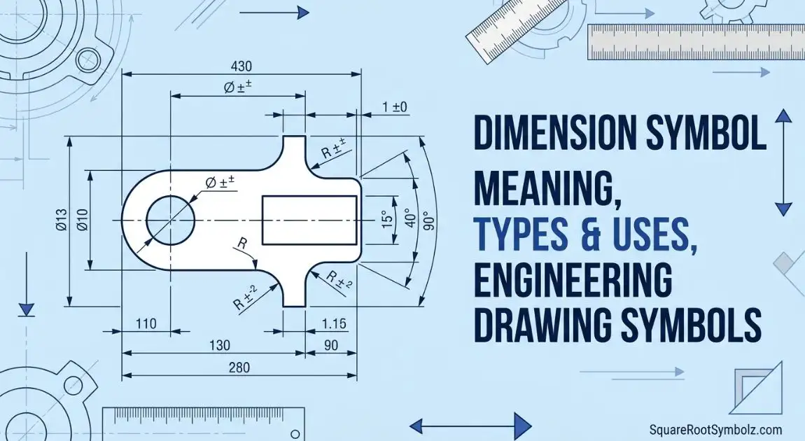
Dimension symbols are an essential part of technical drawings, engineering drawings, and manufacturing documentation. They communicate precise measurements, tolerances, and geometric requirements without relying on lengthy explanations. Whether you’re a student, engineer, machinist, CAD designer, or manufacturer, understanding these symbols helps you read and create accurate drawings.
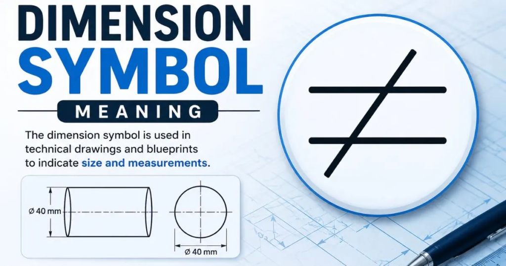
In this guide, you’ll learn what a dimension symbol is, the most commonly used symbols, their meanings, practical applications, and how they’re used in GD&T (Geometric Dimensioning and Tolerancing), CAD software, and technical documentation.
What Is a Dimension Symbol?
A dimension symbol is a standardized graphical symbol used to define the size, shape, location, or geometric characteristics of a feature on an engineering or technical drawing. Instead of writing complete descriptions, engineers use symbols to communicate information quickly and consistently.
These symbols follow international standards such as ISO, ASME Y14.5, and other engineering drafting standards, ensuring drawings can be understood worldwide.
Why Are Dimension Symbols Important?
Dimension symbols help engineers and manufacturers:
- Communicate measurements accurately.
- Reduce misunderstandings during production.
- Maintain consistency across technical drawings.
- Improve manufacturing precision.
- Ensure parts meet design specifications.
Without standardized symbols, interpreting complex engineering drawings would be far more difficult and prone to errors.
Common Dimension Symbols and Their Meanings
The following table highlights some of the most frequently used engineering dimension symbols and their applications.
| Symbol | Name | Common Use |
| ⌀ | Diameter | Circular holes, shafts, and cylinders |
| R | Radius | Arcs and rounded corners |
| □ | Square | Square-shaped features |
| ↧ | Depth | Hole or slot depth |
| ⌴ | Counterbore | Flat-bottom recesses |
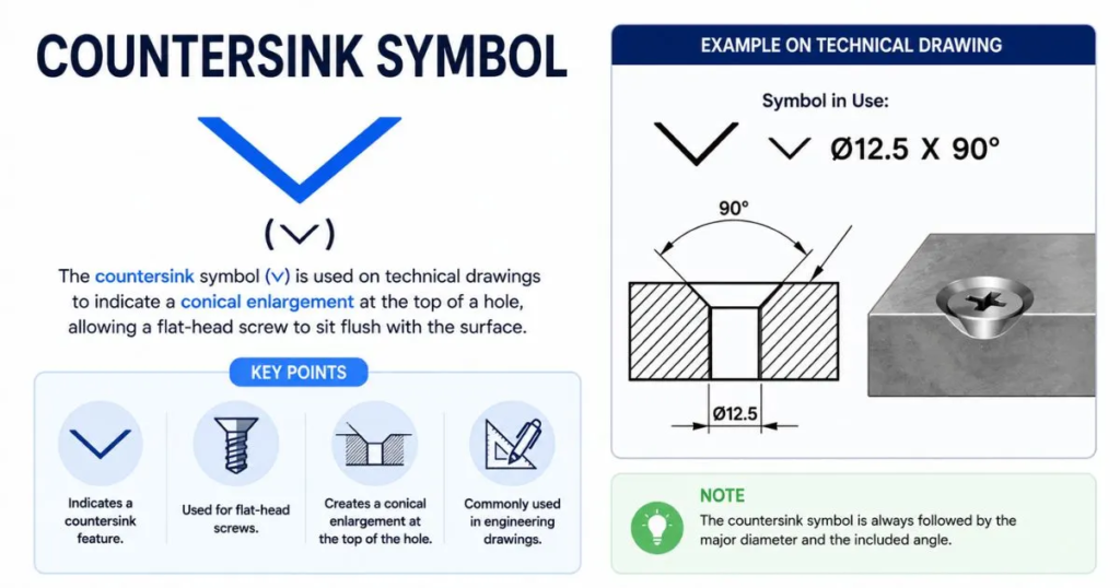
| ⌵ | Countersink | Conical recesses for screws |
| SR | Spherical Radius | Curved spherical surfaces |
| S⌀ | Spherical Diameter | Diameter of spherical features |
These symbols make engineering drawings concise while providing all the information required for manufacturing and inspection.
Types of Dimension Symbols Used in Engineering Drawings
Different symbols represent different types of dimensions depending on the feature being measured.
Diameter Symbol (⌀)
The diameter symbol indicates the diameter of a circular feature such as a hole, shaft, or cylindrical component.
Example:
- ⌀20 mm
- ⌀50 mm
This tells the manufacturer that the measurement applies to the full diameter of the feature rather than its radius.
Radius Symbol (R)
The radius symbol is used when specifying the distance from the center of a circle to its outer edge. Grater than symbol is also used in engineering.
Example:
- R10
- R25
Radius dimensions are commonly found on rounded corners, fillets, and curved surfaces.
Square Symbol (□)
The square symbol identifies features with equal width and height.
Example:
- □15 mm
This indicates that the feature measures 15 mm on all four sides.
Depth Symbol (↧)
The depth symbol specifies how deep a drilled hole, pocket, or slot extends into the material.
Example:
- ⌀12 ↧25 mm
This means the hole has a diameter of 12 mm and a depth of 25 mm.
Counterbore Symbol (⌴)
The counterbore symbol indicates a cylindrical recess designed to accommodate bolt heads or fasteners.
It is commonly used in:
- Machine parts
- Mechanical assemblies
- Industrial equipment
- Automotive components
Countersink Symbol (⌵)
The countersink symbol represents a conical recess that allows flat-head screws to sit flush with the material surface.
It is frequently used in:
- Sheet metal fabrication
- Woodworking
- Aerospace manufacturing
- Mechanical assemblies
Spherical Radius and Spherical Diameter
These symbols define measurements on spherical surfaces.
They are commonly used in:
- Bearings
- Ball valves
- Aerospace components
- Precision-machined parts
Using the correct spherical dimension ensures accurate manufacturing of curved surfaces.
How to Read Dimension Symbols on Technical Drawings
Reading engineering drawings becomes much easier once you understand the meaning of each symbol.
Follow these basic steps:
- Identify the dimension symbol.
- Read the measurement that follows.
- Check the unit of measurement.
- Look for any tolerance values.
- Verify notes or additional specifications.
For example:
⌀30 ±0.02 mm
This means:
- Diameter = 30 mm
- Tolerance = ±0.02 mm
The finished part must remain within the specified tolerance range to meet quality standards.
Another example:
R15
This indicates a radius of 15 mm.
Understanding these symbols helps manufacturers produce parts that match the designer’s intent while minimizing production errors.
Where Are Dimension Symbols Used?
Dimension symbols appear in many industries where precision is critical.
Some common applications include:
- Mechanical engineering
- Civil engineering
- Architectural drawings
- Manufacturing
- Machining
- Automotive design
- Aerospace engineering
- Product design
- Industrial equipment
- CAD (Computer-Aided Design) software
Engineers use these symbols every day to ensure components are manufactured correctly and assembled without compatibility issues.
In modern CAD programs, such as AutoCAD, SolidWorks, Fusion 360, and CATIA, dimension symbols are automatically inserted when creating technical drawings, reducing manual work while maintaining compliance with international drafting standards.

I’m the creator of SquareRootSymbolz.com, where I publish easy-to-understand guides on symbols, Unicode characters, Alt codes, keyboard shortcuts, and copy-and-paste text symbols. My goal is to provide accurate, well-researched, and user-friendly content that helps readers quickly find the information they need.